Reliably deburred parts – more than a hygiene factor
Procedure and methods for successful deburring
Deburring is a necessary evil. Nobody wants it but yet employees in most metal and plastics processing companies fight to master theses tasks on a daily basis. Therefore, deburring is rarely paid enough attention, as it does not directly add value.
We at gravostar technologies have been dealing with this topic on a daily basis for more than 25 years. In 2000, we started to develop tools for milling deburring undefined edges integrated into the metal cutting process. Nowadays, this sector is one of our absolute core competencies.
In the following description, we will demonstrate how burrs form, why it is important to remove them and provide an overview of the different deburring procedures.
General information
Burr formation in the non-cutting manufacturing process
Burrs that occur when casting metals (ferrous or non-ferrous) in the sand casting, chilled casting or pressure die casting procedure are indicated particularly by material residues that escape at the mould joints. The same or similar after-effects also often occur when cutting or die pressing. The same problem sometimes also occurs when manufacturing plastic parts, in the injection die casting and the pressing procedure.
Burr formation when reworking parts
Burrs are formed especially when machining parts (turning, milling, drilling, sawing, etc.). Burrs are also formed when cutting parts to size or separating them via water jet, laser, plasma or flame cutting. Molten material residues can remain stuck on the edges especially when plasma or flame cutting metals.
Why these burrs reworking parts
Burrs that are not removed often pose a massive risk of injury when handling parts (cuts, etc.). Furthermore, workpieces with burrs cannot be processed further in an optimum manner or are completely unusable.
Last but not least, a burr that later falls off can impair the functions of machines or systems, or even cause a complete failure. The absolute worst case scenario that would result from this: recalling entire machine or vehicle series.

If you have unsolved deburring tasks or wish to optimise the deburring process for your parts, get in touch with us!
Roland Zahner
Application technology / distribution
Tel. +41 (0) 71 940 06 76
E-Mail: info@gravostar.com
Possible deburring procedures
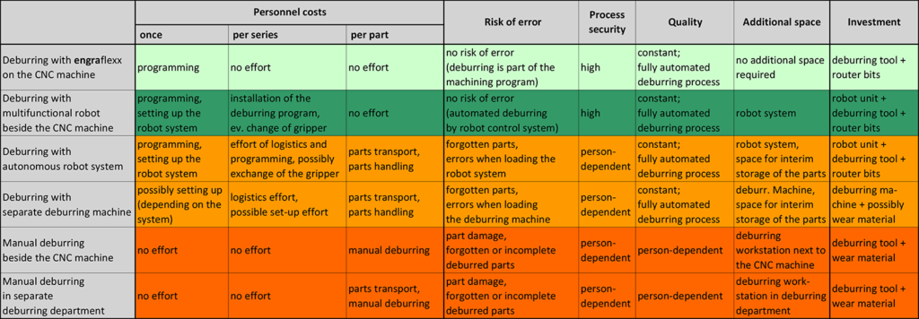
The table below provides an overview of the most common methods for deburring workpieces. The top two methods have a significant difference when compared to other procedures: deburring is fully automated without manual intervention, i.e. each individual workpiece is fully deburred when it comes out of the machining unit and can be processed further immediately. This saves staff costs on the one hand and increases process reliability on the other.
1. Automated deburring integrated into the machining process
This procedure is particularly suitable for part production in CNC machines. The deburring procedure is an integrated part of the machining process. As with all other machining tools, the required deburring tools are stored in the tool magazine and are inserted automatically by the tool changer.
Benefits:
- Parts are finished when they come out of the machine
- Shorter cycle time as a separate work step is omitted completely
- Time saving
- Separate work step is omitted completely
- No additional part handling required
- Cost saving
- Employees can be allocated more efficiently
- Simplified multiple machine operation, etc.
- Relieves employees
- Lower noise levels
- Less dirt development
- Reduced risk of injury
- Highest possible process reliability
- Deburring procedure is part of the production program
- No manual intervention (no incorrect or forgotten deburring)
- Reduced logistical effort
- Organising additional handling or part transport not required
- No additional checks required to establish wheter parts are deburred correctly
- Space saving
- No additional deburring machine
- No separate work station required
- Parts do not have to be stored temporarily prior to machining
- Comparatively low investment:
only deburring tools have to be procured
Disadvantage:
- The machine runtime per manufactured part is extended by the time taken for the deburring procedure
1.1. Machining by milling
Deburring defined workpiece edges
Deburring completely machined parts (with clearly defined edges) is a well established process nowadays in most cases and is normally no longer questioned. This means, it is normal that the parts are of course deburred automatically on the CNC machine using a chamfer milling cutter.
Deburring undefined workpiece edges
This paints a vastly different picture: in this case, the relevant parts are very often deburred in a separate work step, and it is even common that this is done manually.
How and when do undefined edges occur?
- The classic case for this is the edges on cast parts, which occurr during the transition from the machined to the raw cast surface.
- The same topic also occurs when reworking forged or die pressed parts.
- Due to the welding tolerances, the same problems also occur when reworking machine columns or other welded structures.
- Not to forget overlapping holes or hole outlets in angles or curves.
Various tools have been available for deburring hole outlets for some time, which is why we will not deal with this topic extensively here.
Apart from this exception, it was not possible until the early 2000s to deburr workpieces with undefined edges on the CNC machine. At least not if the requirement that all workpiece edges are to be deburred evenly despite size or position differences is to be met. The reason: there simply weren’t any tools available on the market to do this.
In 2007, this shortcoming was rectified: the world first engraflexx EC was presented: the first deburring tool driven via the machine spindle with a deflectable spindle. This enables the workpiece edges to be deburred evenly, even if the programmed contour deviates from the effective workpiece contour.
Various tool designs
Nowadays, the corresponding deburring tools are available in two different deflection processes:
- Tools with a spindle that can be deflected to the side
- Tools with a spindle that is mounted so that it can be moved in the axial direction
One version or the other is preferable depending on the actual application or requirements for the deburring result. Both versions provide virtually the same results in different applications.
Functional principle
The moveable tool spindle is held in the defined initial position at idle using a spring assembly:
- In the machine spindle’s vertical axis in the version with the spindle that can be deflected to the side
- Extended on the limit stop in the axial direction on the tool type with a spindle that can be moved axially
In general, solid carbide router bits are used as the actual milling tools, as used in handheld pneumatic grinders. Due to the spring-loaded, pre-tensioned, flexible spindle mounting, this is simply pushed away by the router bit when following workpiece areas with different masses. As the router bit always presses against the workpiece edge with the same force, it is deburred automatically and evenly everywhere.
The process can be compared with the process in which the employee deburrs the workpiece manually using a pneumatic grinder. But this step is performed automatically in the CNC machine.
Simple programming
The deburring contour can be programmed very easily: the theoretical workpiece contour is programmed first. Radius compensation is used to reduce the milling cutter diameter entry on the machine controller so far that the router bit’s spindle is pushed away slightly at every point on the workpiece contour that is followed (to the side or in the axial direction depending on the tool design, see above).

If you have unsolved deburring tasks or wish to optimise the deburring process for your parts, get in touch with us!
Roland Zahner
Application technology / distribution
Tel. +41 (0) 71 940 06 76
E-Mail: info@gravostar.com
1.2 Deburring with brushes
This is an alternative that is often used on CNC machines. There differences when compared to milling deburring are as follows.
- Fast procedure but only with a limited definition
Following the exact contour is not required, which can save time. However, particularly if the burr formation differs (e.g. wear condition of the machining tool), it is often difficult to ensure even deburring over an extended period. - Brush wear must be observed and rectified
In order to compensate for the brush wear, the brush must be advanced on a regular basis. This should be done permanently in small steps so that the pre-tension can be kept as even as possible. This is particularly difficult in the event of severe wear, as the brush tension also increases. - Contamination should be considered
If abrasive deburring brushes are used on CNC machines, their abrasion is carried along with the coolant. Even if the filtering is good, this together with the contamination can cause increased machine wear. In the worst case scenario, cooling holes in fine tools can even be clogged.
When deburring with brushes on CNC machines, we recommend using steel brushes that are tensioned in an adjustable, spring-mounted holder.
Benefit of the steel brush:
- Grinding material is not deposited on the machine and coolant
Benefit of the adjustable, spring mounted holder:
- Massive increase in process reliability
- The required pre-tension can be adjusted infinitely on the holder
- The spring effect no longer has to be provided by the brush
- The pre-tension pressure always remains the same (regardless of the brush wear)
- Massive relief to the advancement intervals (the spring-loaded holder compensates for the brush wear)
- Significantly easier brush selection
- Cost savings when purchasing brushes
1.3 Grinding, smoothing, lapping, polishing surfaces
This procedure is for surface refinement, which is based on the classic procedure. These processes are normally performed in machines or systems designed especially for this.
However, with the right tool equipment (spring-mounted spindles), this work can also be performed using CNC machines. Finishing shapes and tools, polishing turbine blades, etc. would be particularly feasible.
If abrasive grinding agents are used for this, the machine and coolant contamination must be considered, in the same way as for deburring..
Remark: it is absolutely amazing how the surface can already be improved by using simple steel brushes that are clamped in a spring-mounted tool holder.
engraflexx Deburring tools
In the following document, an overview of the tool designs for use in CNC machines or for use with robots can be downloaded as a PDF
2. Automated in a separate process after part machining
In this process, deburring is performed in a downstream, separate work step regardless of part production or machining. This is performed in specially designed deburring systems or machines, which are often located in separate deburring areas designed especially for them.
Benefits:
- Shorter machine runtime for part machining
- Additional space required
Disadvantages:
- Additional space required
- Separate deburring system
- Parts may have to be stored in between
- Additional staff required
- Part handling
- Additional part transport may be required
- Additional logistical effort may be required
- Regulated sequence organisation must be ensured
- Individual production steps must be tracked
- Reduced process reliability
- Increase risk of errors due to additional manual work process
- Longer total machining time per workpiece
- Relatively high investment (separate deburring system)
2.1 Slide grinding / vibratory grinding
In slide grinding, the workpieces to be machined are moved into a container together with abrasive products (known as chips) and normally with an additive into an aqueous solution as bulk goods. The container’s oscillating or rotating movement rounds or deburrs the workpiece edges due to the abrasive products.
Therefore, in slide grinding, defined deburring does not take place but rather all workpiece surfaces that come into contact with the abrasive products are ground minimally and the edges rounded. The abrasion performance and therefore the degree of deburring can be varied almost infinitely due to the selected abrasive products and additives, as well as the system runtime.

If you have unsolved deburring tasks or wish to optimise the deburring process for your parts, get in touch with us!
Roland Zahner
Application technology / distribution
Tel. +41 (0) 71 940 06 76
E-Mail: info@gravostar.com
2.2 Thermal procedure
This (also known as explosion deburring) is performed by packing the workpieces into a sealed combustion chamber. An oxygen mixture is then fed into the combustion chamber and ignited. The explosive burning process causes an enormous heat (up to 3,000 °C) that only remains for an extremely short time. The fine, protruding burrs therefore melt while the complete workpieces are only heated up slightly to around 60-160 °C.
This procedure is used particularly for workpieces with internal burrs, where mechanical deburring is not possible due to the inaccessibility.
2.3 Water jet deburring
In water jet or high pressure deburring, a water jet with a pressure of several hundred bar is guided onto the location to be machined, causing the protruding burrs to be separated.
This procedure is particularly suitable for workpieces with locations that are difficult to access.
2.4 Electrochemical deburring procedure
In this electrochemical deburring procedure, targeted material removal is enabled by anodic material break-up.
This deburring procedure is particularly useful wherever hole transitions have to be rounded in a targeted manner, such as on distribution units for hydraulic systems.
Stay up to date
With the gravostar e-mail newsletter you will regularly learn everything about process-integrated part marking or automated deburring.
3. Robotic deburring
The actual deburring procedure is normally performed using a deburring tool by milling, brushing or grinding here. A robotic deburring system can basically be laid out according to the following two designs:
- Tool-guided: the deburring tool is attached to the robot and is guided along the workpiece edges using the robot arm. This layout is used particularly if large and heavy parts have to be deburred.
- Workpiece-guides: in most deburring tasks performed by the robot, the deburring unit is fixed and the parts to be deburred are guided by the robot.
This arrangement has many benefits:
- One workpiece can be moved past several different deburring stations in the same deburring process.
- The robot can be used for part handling at the same time. This means that it can perform loading and unloading work on production machines simultaneously or remove the workpieces from a magazine and then set them down in a defined manner again.
Benefits:
- Shorter machine runtime for part machining
- Option to also deburr more complex contours
- Efficient procedure for producing large series
Disadvantages:
- Additional space required
- Separate robot system
- Additional handling unit may be required
- Accessibility to the machining machine may be limited
- Relatively high system complexity
- Additional system or several linked systems
- Increased maintenance and repair susceptibility
- Limited flexibility
- High costs for retroactive product conversion
- High investment costs and planning effort
- Robot and deburring unit
- Additional handling unit may be required

If you have unsolved deburring tasks or wish to optimise the deburring process for your parts, get in touch with us!
Roland Zahner
Application technology / distribution
Tel. +41 (0) 71 940 06 76
E-Mail: info@gravostar.com
3.1 Deburring units or tools
Depending on the respective deburring tasks, different deburring units or tools are used. These can either be attached to the robot, the system or installed on the ground as described above.
The following is a selection of typical deburring units or tools for robotic systems:
- Deburring spindle (fixed or spring-mounted)
- Milling spindle, drilling spindle or grinding spindle
- Belt grinding units
- Brush units
If different deburring tasks are to be performed with different spindles or units on large workpieces, there is the option of equipping the robot with a tool changing unit. This enables the robot to collect the required unit from the tool magazine and to put it back after use.
Deflectable tool spindle
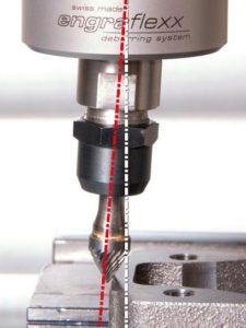
One characteristic is that there are often small or large deviations between the deburring tool and the workpiece edges to be deburred. There may be different reasons for this:
- The workpieces are generally tensioned or collected by the robot gripper again, which often causes position differences to occur.
- In comparison to CNC machines, robots generally have lower stability and precision due to their design. The consequence: Inaccuracies when following the deburring contour.
- There is only a limited possibility to program the exact workpiece contour depending on the robot controller’s programming system.
- Workpieces (e.g. cast or forged parts, etc.) are deburred, which already have certain dimensional deviations.
For this reason, deburring tools with deflectable spindles are normally used for deburring tasks.
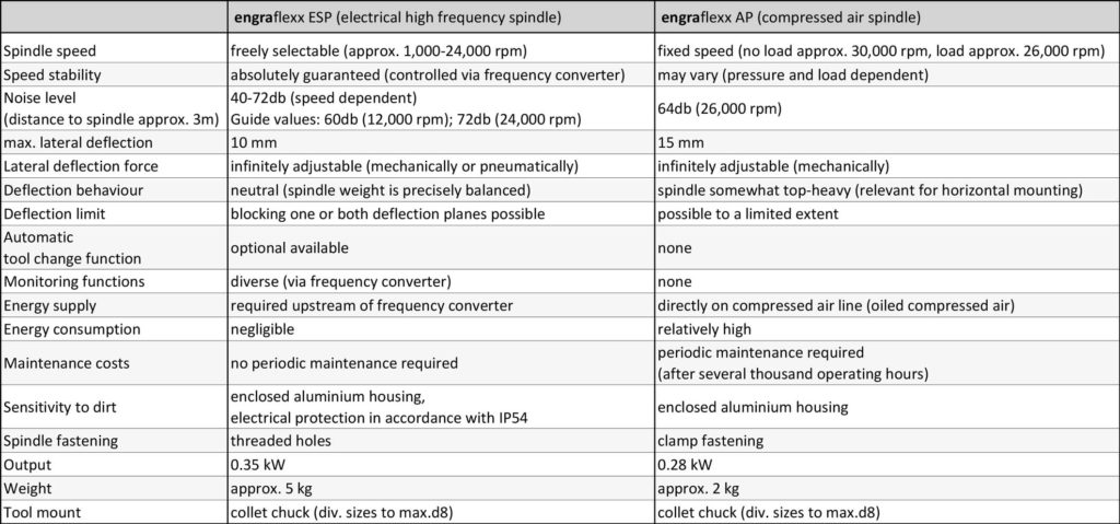
These are often complete units with an integrated drive spindle, which are stored flexibly in the housing. For a long time, these types of spindle units were only offered with an integrated compressed air spindle. Deflectable spindle units with electrical spindles (generally high frequency spindles) have been available for several years. The electrical spindles are significantly more economical in comparison to spindles driven by compressed air, particularly with regard to the running costs (energy consumption and maintenance costs) (see the following table).
Comparison: Electrical spindle– compressed air spindle
Router bits and grinding tools
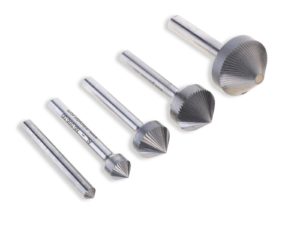
As actual deburring tools , solid carbide router bits of different sizes and shapes are used. Particularly when using in flexible deburring spindles, the deburring result depends significantly on selecting the suitable deburring tool.
For this reason, it is important to work with the supplier that delivers the suitable tools in addition to the deburring spindles. Of course, this also includes the corresponding technical support. In other words, the optimum supplier does not just sell tools but offer their customers a complete solution to the problem.
Deburring brushes
There is an almost endless number of deburring brushes available on the market. There are also many specialists who offer individually designed, customer-specific special brushes. All are justified, as the requirements for deburring brushes are very varied.
However, a relatively simple measure can be taken to simplify the complexity of deburring brushes: clamp the brush into a spring-mounted tool holder rather than rigidly. If this also has an adjustable spring pre-tensioning force, a standard brush can often be used to achieve deburring results that you could never dream of. The reason: the spring force no longer has to be applied by the brush but it is adjusted individually to the required dimension on the tool holder. At the same time, wear compensation is also included and the pre-tension pressure is always the same regardless of the wear to the deburring brush. This increases the system’s process reliability massively.
3.2 Grinding, smoothing, lapping, polishing surfaces using a robot
This procedure is for surface refinement. These processes are very often performed in machines or systems designed especially for this.
However, with the right tool equipment (spring-mounted spindles), this work can also be performed using robots. Finishing shapes and tools, polishing turbine blades, etc. would be particularly feasible.

engraflexx Deburring tools
In the following document, an overview of the tool designs for use in CNC machines or for use with robots can be downloaded as a PDF
4. Manual deburring
This procedure is still very widespread even today. Depending on the material, workpiece shape, severity of the burrs, etc., different mechanical deburring procedures are used.
The requirements for high-quality manual deburring are often underestimated. In particular, as the work is rather unattractive, noisy and causes dirt, but still requires high concentration and lots of technical skill.
Small deburring jobs are often performed in conjunction with part machining by the machine operator directly next to the machine. If more time is required or more complex contours have to be processed, this is normally performed in separate deburring departments.
Benefits:
- Efficient procedure for individual parts or small series
- No or minor setup and preparation work
- Deburring can be performed partially or according to the situation
- Immediate inspection of the deburring
Disadvantages:
- Comparatively expensive (staff-intensive)
- Not very attractive work (loud, dirty)
- Unclear process reliability, as it depends on the employee
- Forgotten or insufficiently deburred areas
- Risk of part destruction due to careless deburring
5. Advantages and possibilities of the engraflexx deburring tools
First of all, the following question should be clarified: what is actually the special feature of these deburring tools and what are their advantages? The uniqueness lies in the movable deburring spindle, which is flexibly fitted in radial or axial direction depending on the respective tool design. The resulting advantage: dimensional and positional differences of the edges to be deburred are automatically compensated, so that the complete part contour is always deburred evenly. This is particularly invaluable when deburring reworked castings, etc.
Saving of manual deburring process
Does it happen in your company that cast, pressed or flame-cut parts are deburred manually after machining?
By using engraflexx deburring tools, the undefined edges of these parts can also be deburred automatically directly on the CNC machine. The procedure is basically the same as for conventional deburring of defined edges using deburring cutters. This means: the parts come out of the machine already deburred.
Increase of the process reliability
Even the most reliable employee makes a mistake now and then. In connection with deburring, this means that parts are not deburred correctly or possibly not at all. In some cases, individual workpieces may even have to be discarded or reworked due to careless deburring (e.g. if sealing surfaces have been damaged). All these sources of error are eliminated with an automated deburring process.
Relief for employees and cost reduction
In most cases, manual deburring is done by means of hand grinders etc. next to the CNC machine. This exposes the employees to unnecessary additional stress due to noise and dirt. In addition, there is a permanent risk of injury due to slipping of the deburring tool or flying chips.
Due to the additional work such as providing the parts, loading and unloading the machine, checking the parts, etc., the production workers are under increased pressure. This pressure is further increased by any additional machine operation, as a result of which it can happen that a machine cannot continue to work due to a lack of employee capacity because the parts to be processed have not yet been clamped.
Last but not least, it is no longer appropriate today for recurring tasks to be carried out manually, which can be automated. Be it from the point of view of competitiveness or the optimal use of employee potential and motivation.
Product advantages
The advantages of engraflexx deburring tools conveniently in a PDF for downloading
With more than 25 years’ experience, we have become experts in the deburring sector. Our core competence is in the area of mechanical deburring procedures that are integrated into the machining process directly on the CNC machine or immediately afterwards using robots.
By passing on this experience, we wish to help interested users to optimised their deburring process sustainably. The consequences: Reduced production costs and increased process reliability for the entire production process.

If you have unsolved deburring tasks or wish to optimise the deburring process for your parts, get in touch with us!
Roland Zahner
Application technology / distribution
Tel. +41 (0) 71 940 06 76
E-Mail: info@gravostar.com
PS: during our consultation meetings, our focus is always on the customer’s tasks and not on our tool solutions. Specifically this means: if a task is solved in a more optimum manner using a different procedure, we will inform you as the prospective customer even if we would therefore not be able to sell our tools.
This corresponds to our company philosophy that places sustainable work that is based on trust over short-term earnings. Furthermore, we are obliged to do this due to our expert status.
Stay up to date
With the gravostar e-mail newsletter you will regularly learn everything about process-integrated part marking or automated deburring.
